ERUI:EFFICIENT SUPPLY CHAIN

Efficient Removal of Deeply Plugged Oil Well

1. Category of Causes for Deep Oil Well Plugging

1.1 Category of oil well plug causes:

i. Mud loss and sludge plug of formation in the period of well drilling and completion.

ii. Poor matching of external liquid with reservoir and fluid leading to clay swelling or sediment.

iii. Throat plugging by accumulation of foreign SS or solid impurities.

iv. Throat plugging by migration and accumulation of particles (including interstitial material and fine sand) in the formation Chemical water plugging of the high water containing section in the early stage.

1.2 Circumstances of deep oil well plugging:

i. Hole & fissure development and serious mud loss.

ii. Super-strong sensitivity, and no oil reservoir protection for a long time.

iii. Loose sand and unreasonable fluid producing intensity for a long time.

iv. Long-term polymer injection, polymer aging and considerable flocculence.

v. Over-high strength of plugging agent in the early water plugging construction.

2. Technical Scheme for Efficient Plug Removal Process

2.1 Conventional plug removal method:

i. Large-displacement acid washing

ii. Fracturing, fracture generation and sand adding

iii. High-energy perforating fun and repeated perforating

2.2 Unfavorable factors of conventional plug removal method:

i. Narrow scope of application and short effective period

ii. Complex procedure and high operating cost

iii. Small treatment radius and poor effect 

2.3 Advantage of Hydraulic shaped charge multi-point sand blasting perforating plug removal process:

i. Wide scope of application and long effective period (suitable for sandstone, limestone, etc.) 

ii. Simple procedure and low operating cost (completion in several hours)

iii. Long treatment radius and good effect (treatment radius above 1m and maximum shaped change of 0.8m)

2.4 Technical principle of Hydraulic shaped charge multi-point sand blasting perforating plug removal process:

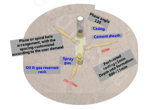
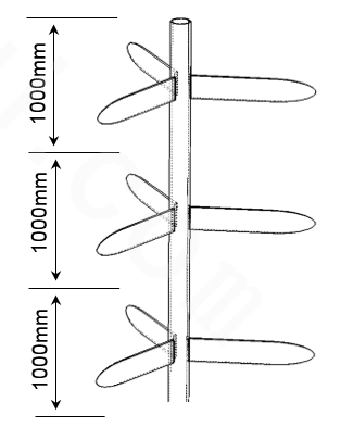
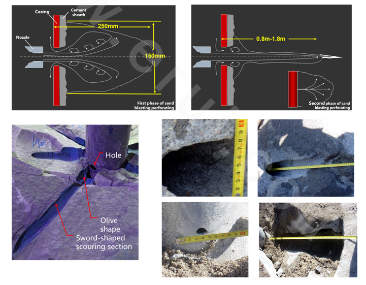
For the hydraulic shaped charge multi-point sand blasting perforating technology, high-pressure sand water is used for positioned spraying of oil reservoir. Under the tubing pressure, the spray gun moves up and down along the axis, cutting the casting, cement sheath and surrounding rock, forming 3 12.15mm (W) and 200mm (H) macroscopic long seams with the angle of 120° and a flat spindle drainage channel with the depth above 1m.
Its open area on the casing and the effective seepage area in the formation are much larger than the 102-shape seepage area of 127 perforating gun. In addition, sand blasting perforating has no compaction zone of conventional perforating, which can effectively penetrate complex pollution zone of ring well. The single-hole permeability is several times higher than conventional perforating. The flow conductivity is dramatically improved under the same production pressure difference.

From the perspective of rock mechanics, the seam of well wall is shaped as a flat oval spindle, which will loosen the rock strata around the seam and reduce its stress, rising the permeability of surrounding rock and achieving the purpose of production increase and injection increase of deep plug removal.

No matter casing and cement sheath or perforating duct in the formation are much larger than the duct generated by traditional perforating process, which effectively improves the problem of shaft friction and sand plug caused thereof, and avoids bending of fissure as jet flow perforating will change with rock surface stress of the formation in the duct, making it more compact.

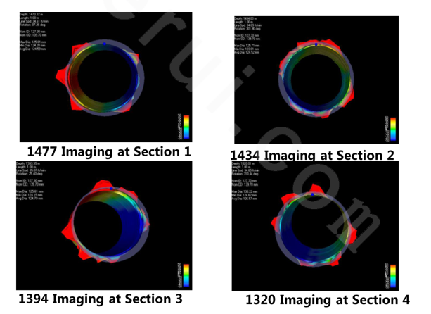
MIT multi-arm imaging logging at Well XX indicates that the casing is completely perforated open.

2.5 Tubular column structure and auxiliary tools:

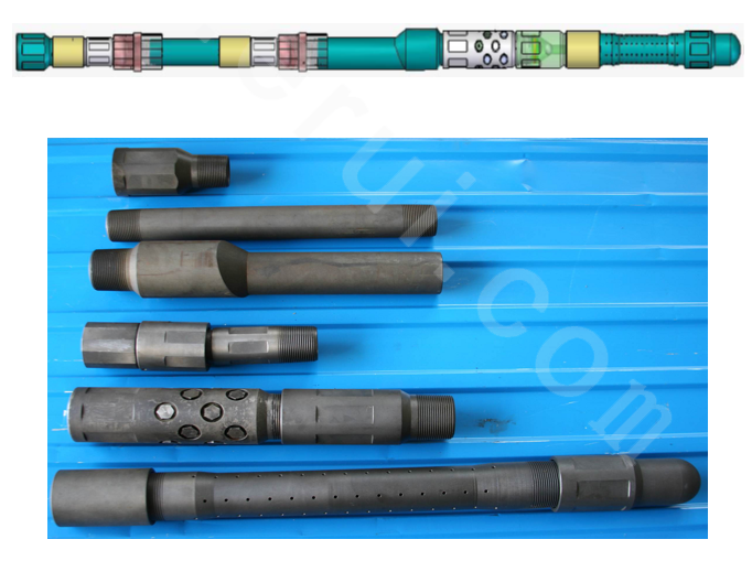
This tool mainly consists of spray gun, restorer, mover, positioning nipple, ball seat and centralizer. 2mm gauze element filter shall be provided on the ground.
For the present karat apply sprayer with extremely high wear-proof and extremely strong anti-return splash capacity, the service life is improved by 5-10 times when compared with the existing nozzles. The single-nozzle sand capacity is over 50m3. One-off RIH can realize the sectional treatment from decade meters to dozens of meters. Great reduction is made to the single-layer perforating cost and the single-well construction period.

2.6 Process technical indexes:
ⅰ. Nozzle dimension: 3×Ф4.0mm
ⅱ. Working pressure: 25-35MPa (the oil tube and annular friction pressure shall be attached to the wellhead pressure)
ⅲ. Sand ratio: 4-8%
ⅳ. Sand quantity of each layer: 1.5-2m3
ⅴ. Perforating liquid: clean water, workover liquid or acid liquid
ⅵ. Quartz sand grain size: 0.4-0.8mm (20/40 mesh)
ⅶ. Mover control mode: oil tube pressure
ⅷ. Nozzle flow: 450-550L/min (3×Ф4.0 nozzle)
ⅸ. Perforating diameter at each point: casing 4.5mm, formation 12-22mm
ⅹ. Height of multi-point perforating in one group: 200mm
ⅹi . Perforating depth: 800mm-1,800mm
ⅹiii.  Auxiliary tool: positioning nipple
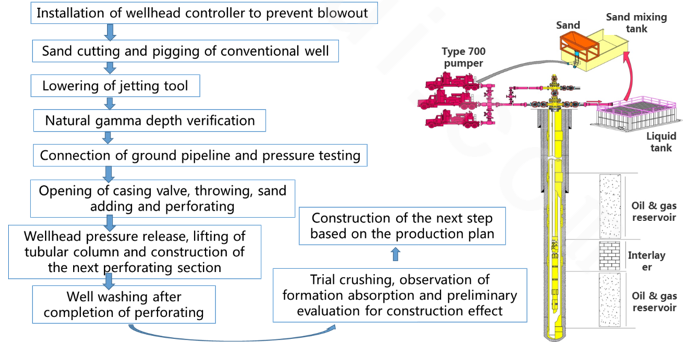
ⅹⅳ. Equipment demand: three Type 700 pumpers, one 2m³ manual sand hopper, one 5m³ tank, one 13m³ water tank, and 2 sets of high-pressure tee and valve; tripping of tubular column needs to coordinate with the workover rig.

3.Typical Field Implementation Case Effect

3.1 Production increase in sensitive plug removal of Well Case1:

As interpreted in the electrical logging data of this well, the permeability is 102md. The shale content is as high as 27.5%. The oil reservoir thickness is 1.0m. The original static pressure is only 9.0MPa. There is no corresponding well supplementary formation energy. Conventional perforating process is applied in well completion. In the production process, the oil reservoir was not applied. Therefore, it is difficult to give full play to the productivity. The liquid supply capacity is poor. The oil yield is only 1.2t/d. The hydraulic shaped charge sand blasting perforating technology is adopted. The construction well section is 1,397.0-1,399.0m. It is perforated for 1 time, with the diameter of 15-20mm, the height of 200mm, the perforating depth of 1,700mm, the nozzle diameter of ф3.5mm and the sand consumption of 4t. After the construction, the liquid yield is 44.3t/d. The oil yield is 6.8t/d. The moisture content is 84.5%. The daily oil yield is increased by 4.7 times on average. Thus, it is obvious that this technology can give full play to higher potential of thin sensitive reservoirs. For the thin layers with the thickness of 1.0m, it has more advantages than conventional perforating means.

3.2 Production increase in sensitive plug removal of Well Case 2:

As interpreted in the electrical logging data of this well, the permeability is 102md. The shale content is as high as 27.5%. The oil reservoir thickness is 1.0m. The original static pressure is only 9.0MPa. There is no corresponding well supplementary formation energy. Conventional perforating process is applied in well completion. In the production process, the oil reservoir was not applied. Therefore, it is difficult to give full play to the productivity. The liquid supply capacity is poor. The oil yield is only 1.2t/d. The hydraulic shaped charge sand blasting perforating technology is adopted. The construction well section is 1,397.0-1,399.0m. It is perforated for 1 time, with the diameter of 15-20mm, the height of 200mm, the perforating depth of 1,700mm, the nozzle diameter of ф3.5mm and the sand consumption of 4t. After the construction, the liquid yield is 44.3t/d. The oil yield is 6.8t/d. The moisture content is 84.5%. The daily oil yield is increased by 4.7 times on average. Thus, it is obvious that this technology can give full play to higher potential of thin sensitive reservoirs. For the thin layers with the thickness of 1.0m, it has more advantages than conventional perforating means.


You can click to >>contact us<< or directly by phone or email:
TEL.: 400-820-9199
E-mail: sales@erui.com

0.098671s