1. Technical state
Inject into water (steam, gas) well. Multiple injections. Each follows the preceding section (fracture channel). If water (steam, gas) can’t equally reach the stratum as designed, rapid water (steam, gas) channeling may occur and seriously affect water (steam, gas) injection and cause water-cut quickly rising.
General polymer liquid material plugs the flooding channel of injector by adjusting the viscosity of material and construction parameters. However, the pressure changes during pumping are unpredictable. Profile control agent can not only enter the large flooding channel but also the oil layer of non-flooding channel. As a result, selectivity loses in plugging flooding channel.
The gravitational collapse and inundation of plugging material causes the blocking less effective in the upper part of flooding channel.
2.Material Characteristics
2.1 Consisting of multiple components including of active fiber functional polymer skeletal structure, gelling complex and thixotropic gel, the material can enter preferential path. Gelling functional crosslinking can only enter big channels (or fractures) so it won’t pollute matrix strata. This also helps decrease the plugging agent usage significantly and contributes to the sufficient plugging of main seepage channel in water-flooded layer to ensure the sweep area and the production effect of fracturing wells and water-flooded wells.
2.2 Has liquid fluidity and high thixotropy of solid skeletal structure to ensure fully filling the top part (horizontally) of water (steam, gas) channeling paths or big channels.
3. Technical Indicator
3.1 Use and Usage
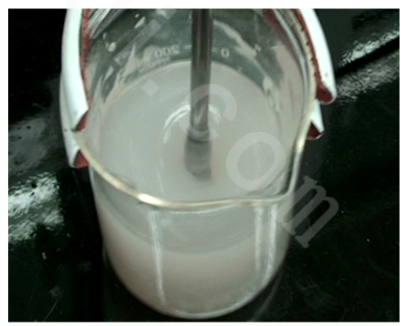
3.1.1 Use: This agent is easy to use. All you have to do is mix it with water in certain proportion to make shutoff agent solution.
3.1.2 Usage: It has the same usage with normal low-temperature shutoff agent. The usage depends on the geologic conditions. The agent usage for dealing with flooding, water channeling and steam channeling in water exit of oil-water well and fracturing fractures is normally one-fifth of that for water shutoff in oil well and profile control well.
3.2 Construction Process
3.2.1 Pull out the original well: Pull out the production string from the well after balanced well flushing.
3.2.2 Drifting: Trip in drift-size gauge tools matching the case to drift to the bottom hole or design location. Employ high-discharge (400-600L/min) direct flushing (no less than a week).
3.2.3 Pressure test of oil tube and case: Oil tube: test pressure 25MPa; steady pressure for 30min. Qualified if pressure drop within 0.5MPa. Case: test pressure 15MPa; steady pressure for 30min. Qualified if pressure drop within 0.5MPa. Packer-type string injection may be employed if there’s oil layer in upper or lower part.
3.2.4 Blank tubing with nib descends the well. Install wells of 250 or 350 type. Screws shall be sufficient and tightened enough. When pump truck has been on the well, surface pipelines shall be connected after passing the pump test and pressure test (test pressure 25 MPa; no piercing or leaking for 1 min). Squeeze shutoff agents, pre-pad fluid and post-pad fluid as designed to substitute the waste water in oil layer and displace the shutoff agent to design location. Employ steady pressure for 24h for it to set.
3.2.5 Test squeeze: Original well string test squeeze. Each pressure stage employs test squeezing for 10min. Pressure gradually increases (5MPa, 10MPa, 15MPa, 20MPa). When pressure climbs over 20MPa and discharge capacity goes lower than 100L/min, then stop squeezing.
3.2.6 Deepen the design depth or the difference between tubing flushing and the artificial bottom hole and granulation surface. Employs high-discharge flushing for 1.5 weeks before pulling out the construction string. 4. Used devices
4.1 Two type 400 pump trucks.
4.2 One set of electric blender or hydraulic blender.
4.3 Three spare watercarts.
You can click to >>contact us<< or directly by phone or email:
TEL.: 400-820-9199
E-mail: sales@erui.com